Transistor As A Switch Circuit Diagram Learn why transistors are used as switches in circuits and how to wire them up with examples. A transistor is a 3-pin device that turns on or off by electrical current and can also amplify signals.

A transistor switch is a circuit in which the collector of the transistor is switched ON/OFF with relatively larger current in response to a correspondingly switching low current ON/OFF signal at its base emitter.. As an example, the following BJT configuration can be used as a switch for inverting an input signal for a computer logic circuit.
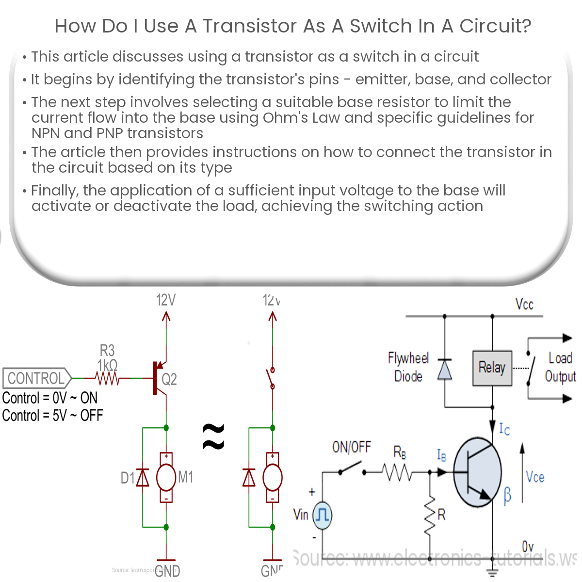
How to Connect a Transistor as a Switch in a Circuit Circuit Diagram
Transistor as a Switch. Basically as per the generations of the electronic circuits gets revolutionized and improved for better and comfortable living the transistors played a prominent role by replacing themselves with vacuum tubes.. This leads to an improvement in efficiency and compression in size. The main functionality of the transistor can be observed either by making it be used for

Many common-purpose transistors will only give you up to 100 mA. So for a current of 1A, it's important to choose a transistor that can handle it. The PNP Transistor as a Switch. A PNP transistor works the same way as an NPN transistor for switching operations, but the current flows in the opposite direction.
The Transistor as a Switch: A Practical Guide for Beginners Circuit Diagram
In Darlington Transistor Switch two NPN or PNP are connected together in a wat that the emitter current of the first transistor T1 becomes the base of the second transistor T2. So the T1 is connected as an emitter and the T2 is common emitter amplifier. Configuration Darlington Transistor Switch . Digital Logic Transistor Switch If the circuit uses the Bipolar Transistor as a Switch, then the biasing of the transistor, either NPN or PNP is arranged to operate the transistor at both sides of the " I-V " characteristics curves we have seen previously. The areas of operation for a transistor switch are known as the Saturation Region and the Cut-off Region. This means
